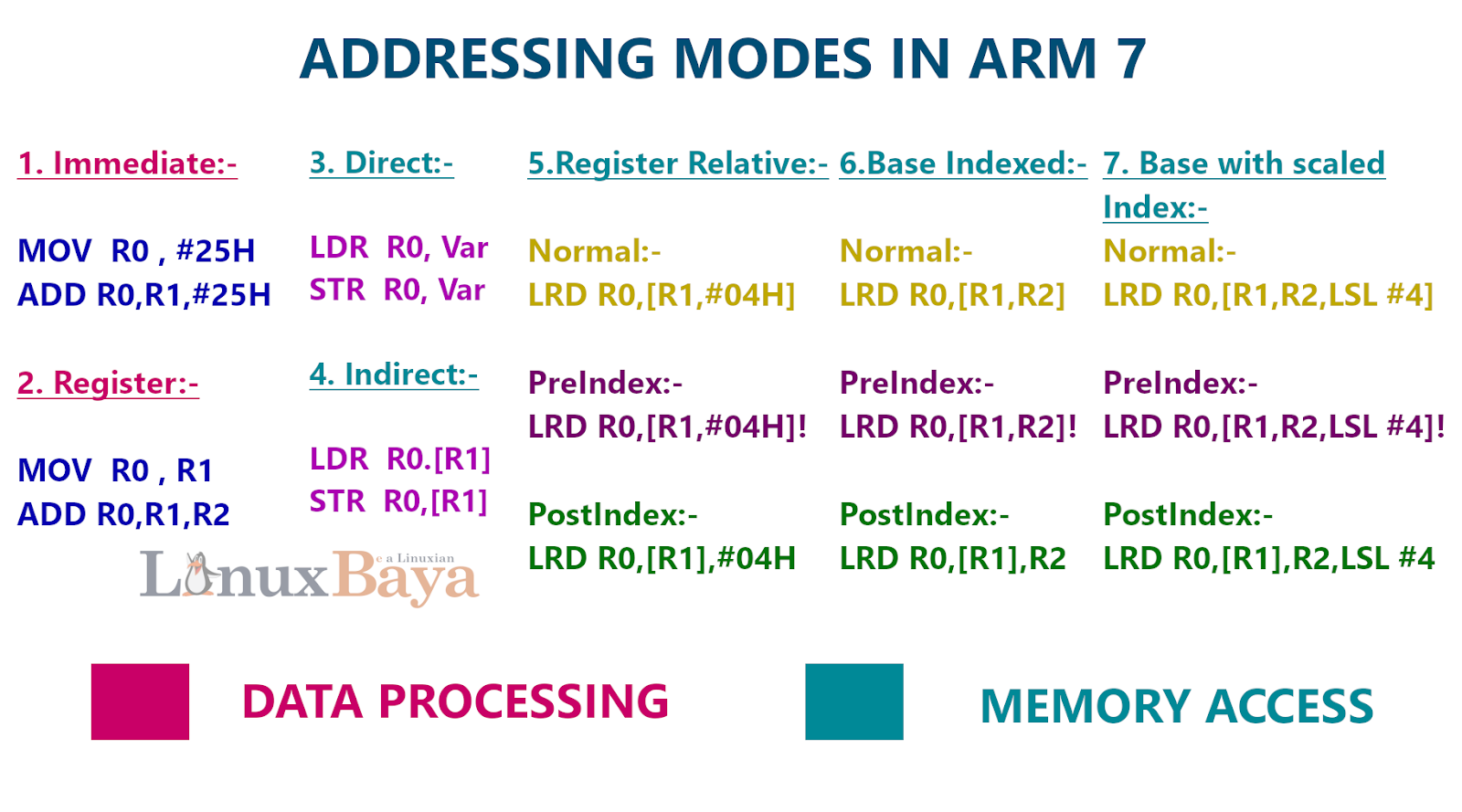
The manner in which an operand is given in the instruction is called addressing mode. The operand is the value on which you want to operate.
We can add 25 with the register R0 and put the result inside R0, or we can move the value to a register and then add the two register. Or we put the value into any memory and give its address to add and so on and so forth,
For Example:-
ADD R0, #25H;
MOV R1, #25H;
ADD R0, R1;
MOV 45H, #25H;
ADD R0, 45H;
So how do I tell the processor that my operand is 25 that is called addressing mode. There is various addressing modes are possible.
1. Immediate Addressing Mode:-
When the data is given in the instruction. ADD R0, #25H, Here the data 25 is given in that instruction. so no extra time required to search for the data. hence it is called immediate addressing mode.
MOV R0, #25H; R0 gets data value 25H
ADD R0, R1, #25H; R0 gets Value of R1 + data value 25H
Note:- If there is '#' at the beginning of any number then is a data or else it is an address.
We know that every instruction is of 32bit so we can only put the 8bit value inside the instruction. because the total size of one instruction is 32bit. If we put a 32bit value inside the instruction then the value itself take all size of instruction there is no space for upcode and register. So in immediate addressing mode always the 8bit value us allowed.
2. Register Addressing:-
Now instead of giving data in the instruction, we give the data using the register.
MOV R0, R1; R0 gets R1 value
ADD R0, R1, R2; R0 gets the sum of R1 and R2
From now we give the data using the memory address.
As we know the only operations are performed by memory are load and store. Hence next 5 Addressing modes are only applicable for Load and Store operations.
As we know the only operations are performed by memory are load and store. Hence next 5 Addressing modes are only applicable for Load and Store operations.
Now the address is going to give the data. When data is in memory.
3. Direct Addressing modes:-
Here the address is going to give the data, When data is in memory. "Var" is the variable that may be assigned with some value. Then Assembler will substitute the address. Remember the address is 32 bit. So assembler will not put the 32bit address. It put the 12-bit Offset. Offset not gives the actual address, it gives the distance from the current location to the location of the variable. 12bit can give the value up to 4k location.
LDR R0, Var; R0 gets data from memory location “Var”
STR R0, Var; R2 will be stored at the memory location “Var”
Note: “Var” is a variable defined in memory
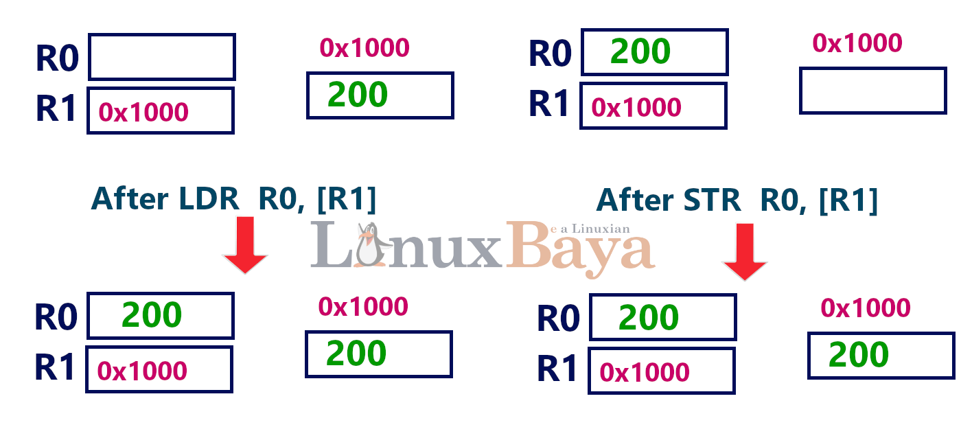
4. Indirect Addressing modes:-
If the variable address is out of the range 4k then put the address in a register and give the register in indirect addressing mode.
R1: - It gives the value.
[R1]: - It gives the address.
LDR R0, [R1]; R0 gets the value pointed by the address inside the register R1.
STR R0, [R1]; The address inside the register R1 is going to get the value of R0.
And another use of Indirect addressing mode is while we use in a loop and increment the Address for each loop, It is sure that each time it can access the next location.
The next 3 Addressing modes are just the extension of the indirect Addressing mode. And each mode has 3 versions.
5. Register Relative Addressing modes:-
Here address of the memory operand is given by a register plus a numeric displacement.
Eg: LDR R0, [R1, #05H] ;
R0 gets data from the memory location pointed by (R1 + 05H)
R1 remains unchanged.
Eg: LDR R0, [R1, #05H]! ;
First: R1 gets R1 + 05H
Then: R0 gets data from the new memory location pointed by R1.
This is called PRE-INDEX Addressing.
Eg: LDR R0, [R1], #05H ;
First: R0 gets data from memory location pointed by R1
Then: R1 gets R1 + 05H
This is called POST-INDEX Addressing.
6. Base Indexed Addressing modes:-
Here address of the memory operand is given by a sum of two registers, where one register
acts as the base, and the other acts as the index register.
Eg: LDR R0, [R1, R2];
R0 gets data from the memory location pointed by (R1 + R2)
R1 remains unchanged.
Eg: LDR R0, [R1, R2]! ;
First: R1 gets R1 + R2
Then: R0 ç data from the new memory location pointed by R1.
This is called PRE-INDEX Addressing.
Eg: LDR R0, [R1], R2; First: R0 get data from the memory location pointed by R1
Then: R1 gets R1 + R2
This is called POST-INDEX Addressing.
7. Base with scaled Index Addressing modes:-
Here address of the memory operand is given by a sum of two registers
The first register acts as a base register. The second register can be scaled by shifting left.
Eg: LDR R0, [R1, R2, LSL #2];
R0 gets data from the location pointed by (R1 + R2 left-shifted by 2)
R1 remains unchanged.
Eg: LDR R0, [R1, R2, LSL #2]!;
First: R1 gets R1 + R2 left-shifted by 2
Then: R0 gets data from the new memory location pointed by R1.
This is called PRE-INDEX Addressing.
Eg: LDR R0, [R1], R2, LSL #2;
First: R0 gets data from the memory location pointed by R1
Then: R1 gets R1 + R2 left-shifted by 2
This is called POST-INDEX Addressing.
Use of base with scaled index:- for example, we want data from location 0x1256. Then we assign a register r1 with 12 and register r2 with 56 then we use the addressing mode.
LDR R0, [R1, R2, LSL #8];
It first left shift the 12 by 8bits and the add the register r2 with r1. now, r1 is pointing to the address 0x1256. Hence r0 get the value from the address 0x1256 that pointed by r1.
It first left shift the 12 by 8bits and the add the register r2 with r1. now, r1 is pointing to the address 0x1256. Hence r0 get the value from the address 0x1256 that pointed by r1.
Other Related Topics:-


