
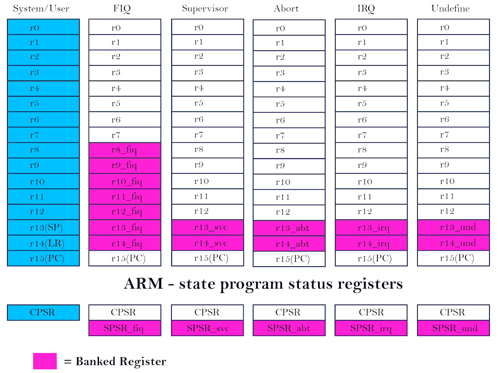
There are 7 modes of operations. In each mode, the programmer has access to 16 GPRS (R0 – R15) and a CPSR (Flag Reg). Additionally, a Saved PSR (SPSR) is also available in all modes except User/ System mode. All registers are of 32 bits. In all modes, the three registers have common functions.
R15: PC (Program Counter)
PC gives a 32-bit address of the instruction to be fetched. This address is put on the address bus and the instruction is fetched from the memory through the 32-bit data bus. PC is periodically incremented after every instruction is fetched. Since all instructions are of 32-bits and are stored at 32-bit aligned locations (multiples of 4), the lowest two bits of PC are insignificant (XX).
R14: LR (Link Register)
It stores the return address (value of PC) when we perform a BL instruction (Branch with the link, like a CALL instruction). While returning back to the main program the value of LR will be put back
into PC.
R13: SP (Stack Pointer)
Holds the address of the top of the stack.
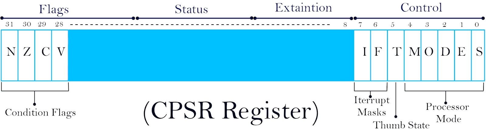
CPSR (Current program status register):
It holds the current status of the program. When an exception/ interrupt occurs, the value of CPSR is saved into SPSR (Saved Program Status Register), before invoking the ISR. While returning back to the main program, the value of SPSR is put back into CPSR to restore the previous state of the original program.
CPSR (Current program status register) holds the current status of the program. When an exception/ interrupt occurs, the value of CPSR is saved into SPSR (Saved Program Status Register), before invoking the ISR. While returning back to the main program, the value of SPSR is put back into CPSR to restore the previous state of the original program.
Mode Bits:
ARM7 can operate in 7 different operating modes.
These bits indicate the current operating mode of the processor.
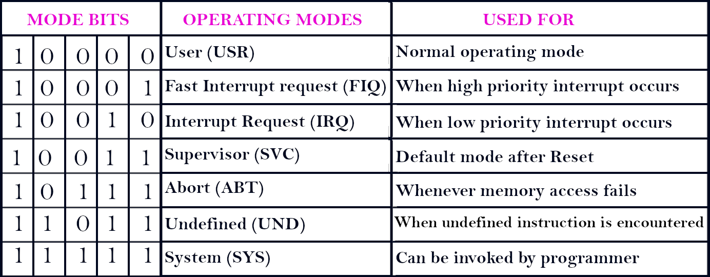
All modes except User mode, are called “Privileged Modes”.
T: Thumb State
If T = 1, then the processor is in Thumb state
If T = 0, then the processor is in normal ARM7 state.
Thumb state is a special state where the “Thumb” instruction set, having 6-bit instructions are used.
This is useful if the memory is implemented as a 16-bit memory.
F: Fast interrupt Mask
If F = 1, then Fast Interrupts are disabled (masked).
If F = 0, then Fast Interrupts are enabled (un-masked).
A fast interrupt occurs through the nFIQ pin.
I: Interrupt Request Mask
If I = 1, then normal Interrupts are disabled (masked).
If I = 0, then normal Interrupts are enabled (un-masked).
A normal interrupt occurs through the nIRQ pin.
Condition Flags:-
V: Overflow Flag
V = 1 means signed overflow occurred
V = 0 means signed overflow hasn’t occurred
C: Carry Flag
C = 1 means carry after MSB
C = 0 means no carry after MSB
Z: Zero Flag
Z = 1 means the result is zero.
Z = 0 means the result is non-zero.
N: Negative Flag
If N = 1, the result is negative
If N = 0, the result is positive.
(Note: This flag always indicates the correct sign in spite of an overflow, unlike Intel’s Sign flag.)
Bit No 27: Saturation Flag / Q flag
In “E” versions of ARM7 (DSP Extensions), this flag indicates if a “saturation” has occurred.
If Q = 1, then arithmetic saturation has occurred. (All 1s rolls over to All 0s)
If Q = 0, then no such saturation has occurred.
This is useful in some signal processing applications.
(Note: Not applicable in ARM7TDMI, hence not shown in the diagram)
Additionally, there are some Banked Registers that are available in specific operating modes.
FIQ mode:
R8 – R14 provides a fresh set of GPRS. This eliminates the need to store the original values of these registers elsewhere and hence makes the execution of the ISR faster.
All the other privileged modes get their own versions of SP and LR (R13 and R14).
This gives a total of 37 registers all 32-bits each.
Also, Read👇


